Short answer. Exhaust back pressure is the gauge pressure in the exhaust right after the engine: at the turbocharger outlet on a turbocharged engine. It equals the total pressure lost through everything downstream: the flexible connector, piping and bends, the silencer, any aftertreatment and the rain cap. Every engine has a manufacturer-specified maximum, and exceeding it reduces power and raises fuel consumption and exhaust temperature.
Back pressure or pressure drop?
The terms get mixed up. Strictly, back pressure is one number for the whole exhaust system, taken at the engine’s exhaust outlet. Each component has a pressure drop, or pressure loss, and the back pressure is their sum. DieselNet’s technical guide recommends keeping “back pressure” for the system and “pressure drop” for the parts, and this article does the same.
Why the engine has a limit
The engine has to push its exhaust out against that pressure. Higher back pressure means more pumping work, less energy available to the turbocharger and hotter exhaust. So every engine manufacturer publishes a maximum exhaust back pressure in its installation data. Exceeding it reduces power and raises fuel consumption and exhaust temperature.
This article deliberately gives no number. Limits differ by engine model, rating and configuration, and the value that matters is the one in the installation data for the exact engine.
Where it is measured
At the point the engine manufacturer specifies, typically on a straight length of pipe close to the turbocharger outlet, with the engine at the load and speed the specification calls for. A reading taken further downstream misses the losses upstream of the tapping point.
What adds to it
- Pipe friction, which grows with pipe length and falls steeply as the diameter increases
- Bends, elbows and transitions: each adds a loss, and tight bends and abrupt changes of section add more than long-radius bends and gradual transitions
- The flexible connector, which is short but corrugated, and restricts more if it is damaged, collapsed or misaligned
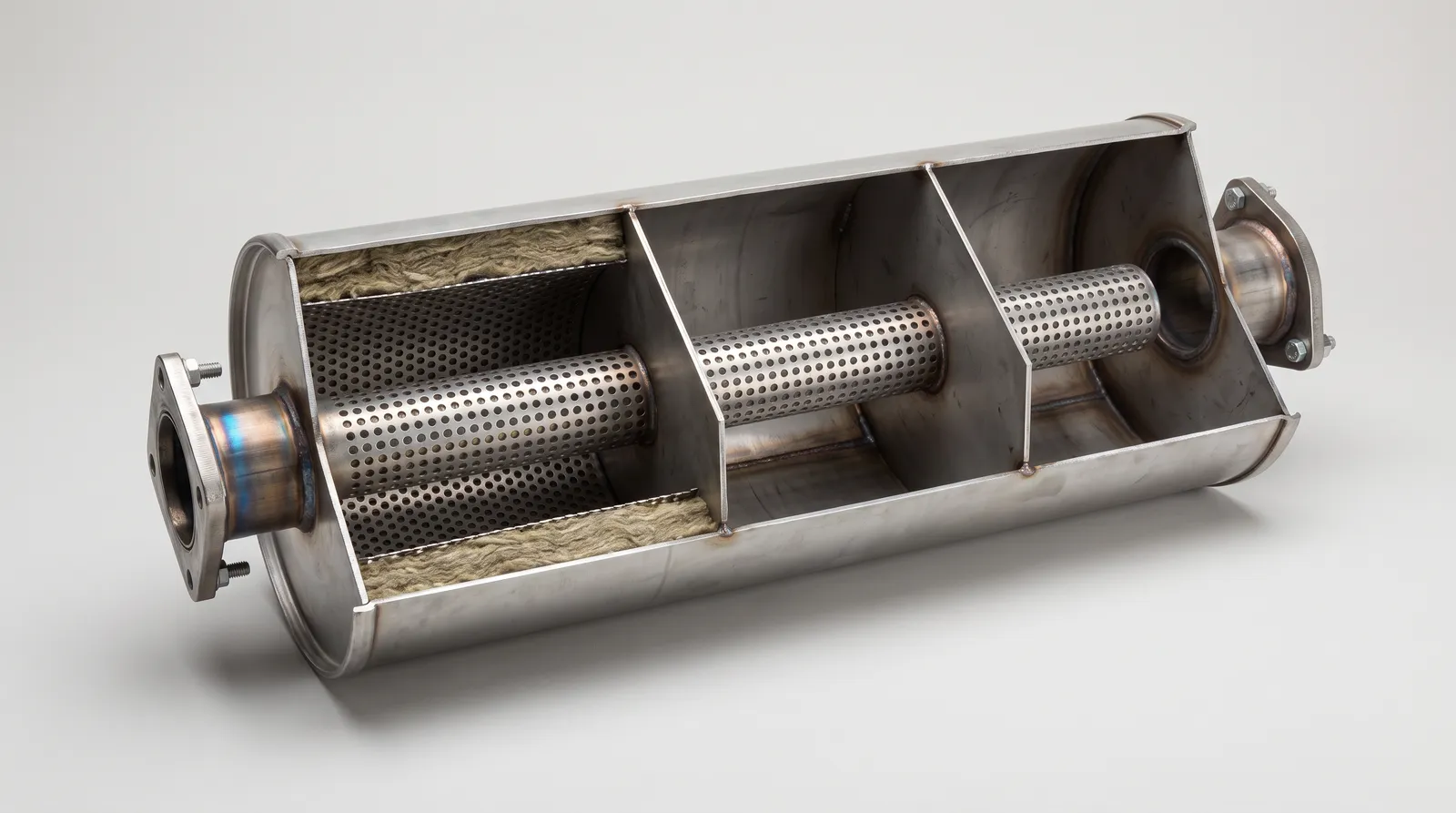
- The silencer, often the largest single loss, and the one that trades directly against noise
- The rain cap or outlet fitting at the end of the stack
- Aftertreatment, where fitted, with a loss that can change with operating conditions
How it is calculated
The calculation adds up the losses at the full-load exhaust flow and temperature from the engine data. Each length of pipe and each fitting loses pressure in proportion to the dynamic pressure of the gas, ½ρV²:
Δp(pipe)     = f × (L / D) × ½ρV²
Δp(fitting)  = K × ½ρV²
Back pressure ≈ ΣΔp(pipe) + ΣΔp(fittings) + Δp(silencer) + Δp(rain cap)
f: friction factor, from the Reynolds number and pipe roughness · L, D: pipe length and inside diameter · K: loss coefficient of a bend or fitting, from published data · ρ: gas density at the exhaust temperature · V: mean gas velocity. Silencer and rain-cap losses come from the supplier’s data at the stated flow, or from a model; add any aftertreatment the engine has.
Three things follow from the formula.
- Temperature matters. Exhaust gas is hot, so its density is low. For the same mass flow, lower density means higher velocity, and the pressure loss rises with it. Use the exhaust temperature from the engine data, not ambient conditions.
- Diameter matters most. For a given flow, velocity in a pipe varies with the inverse square of its diameter, so a modest increase in pipe size cuts the friction loss sharply. Engine installation manuals often convert bends into an equivalent length of straight pipe and size the pipe from the total.
- Losses add up. The silencer doesn’t get the whole allowance; it gets what the piping, bends, connector and cap leave.
When a hand calculation is enough, and when it isn’t
For a conventional layout with published loss coefficients and the silencer supplier’s pressure-drop data at the right flow and temperature, the calculation above is quick and adequate. It becomes unreliable when the geometry has no published data, such as a custom silencer or an unusual outlet or rain cap, or when components are close enough together to change each other’s flow. Then CFD of the actual geometry predicts the pressure drop and shows where the losses occur (CFD flow and pressure drop).
How to bring back pressure down
- Increase the pipe diameter, shorten the run and remove bends; where bends are unavoidable, use long-radius bends.
- Choose a silencer with less pressure drop for the attenuation the site needs. That is a trade-off judged on both measures together (attenuation and back pressure, side by side).
- Review the rain cap and outlet arrangement.
- Check the flexible connector and any aftertreatment for damage or loading.
Confirm it on the finished installation
Calculations and simulations predict; a measurement confirms. Installation guidance calls for measuring back pressure on the finished system at the specified point and load, with instruments suited to the exhaust pressure and temperature.
Related services
Read next
- CFD Flow & Pressure DropPredicting back pressure and where the losses occur, before hardware exists.
- Silencer design: attenuation and back pressureSilencer attenuation and back pressure, side by side.
- Generator Noise RetrofitsChanging the silencer on an installed set without breaking the back-pressure limit.
Sources
- DieselNet Technology Guide, Engine Exhaust Back Pressure (H. Jääskeläinen)
- Scania, Exhaust system installation manual, Issue 10 (industrial and generator-set engines)
- Aurora Generators, Generator exhaust backpressure
- J. M. Cimbala, Penn State University, Fluid Mechanics Lesson 08F: major and minor losses in pipe flow