Why enclosure airflow needs its own analysis
An engine-driven generator set rejects its engine heat through a radiator, and the radiator fan has to move that cooling air through the whole enclosure or room. Cooling systems are rated to carry full load up to a stated ambient temperature, and anything that restricts the cooling air eats into that margin. Past it, the engine can overheat and shut down.
The enclosure has to pass large volumes of cooling and combustion air while keeping engine and radiator-fan noise inside, and every acoustic feature on the air path adds restriction. That is why the airflow is analyzed alongside the noise design, not after it.
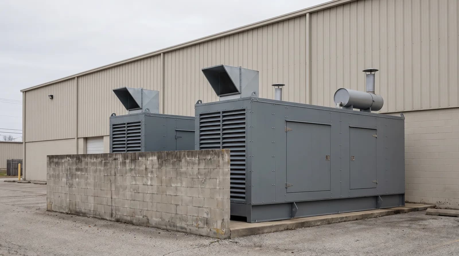
The cooling-air path
Air enters through the inlet louvers, often with an inlet silencer behind them, passes over the alternator and engine, and is pushed by the radiator fan through the radiator and out through a splitter silencer and a discharge louver or hood. The engine’s combustion air is usually drawn from the same enclosure.
Restriction: what the radiator fan can push against
An engine-driven radiator fan delivers its rated airflow only against a limited external restriction, which the generator-set manufacturer specifies. Inlet louvers, inlet and discharge silencers, discharge hoods, screens and any ducting all add to it. Longer splitter silencers with narrower airways attenuate more but add pressure drop, and the whole ventilation path must stay within the manufacturer’s allowable cooling-air restriction. Exceed it and the airflow falls, the radiator runs hotter, and the set may have to be derated.
CFD predicts the pressure drop through each element at the design airflow, so the total can be checked against the allowance and the largest contributor found before louvers and silencers are ordered.
Generator rooms
When the set is indoors, the building is the enclosure. Ventilation air comes in through intake openings and louvers, crosses the room and the set, and the radiator fan pushes it out through a discharge duct or plenum and a discharge louver in the outside wall. The engine’s combustion air is drawn from the same room. On a noise-sensitive site, intake and discharge attenuators or acoustic louvers are added to those openings, and they can be long.
Everything on that path counts against the same limited fan restriction: intake louvers and dampers, attenuators, the discharge duct and the discharge louver. Keeping the air velocity through the attenuators within limits keeps their pressure drop down, which is why the opening sizes and the attenuator selection are decided together. CFD predicts the airflow and pressure drop through each element of the room’s path; the acoustic model predicts what the attenuators and louvers do to the noise leaving through the openings.
Airflow and noise are one design
The louvers, splitters, attenuators and hoods that keep the noise in are the same elements that restrict the cooling air. On a site with a sound limit, the acoustic model sizes the attenuation and the airflow model checks what it costs in restriction, so the layout chosen is the quietest one that still cools at full load. A quieter layout that starves the radiator is not a solution. Generator and engine noise reduction
Questions a study answers
- Will the radiator get enough air at full load once the planned louvers, splitter silencers and hood are fitted?
- How much restriction does each element add, and which one should change first?
- In a generator room, how much do the intake louvers, attenuators, radiator discharge duct and discharge louver add between them?
- Where is the air moving fastest through louvers and splitter airways, and is an opening too small for the airflow it has to pass?
- Which ventilation-path layout is quietest while still giving the radiator enough air at full load?
What to send, and what comes back
What you send
- The generator-set manufacturer’s cooling data at the rating of interest: required airflow and allowable external restriction
- Enclosure or generator room geometry: intake and discharge openings, the internal layout around the alternator, engine and radiator, and any discharge duct
- The louvers, splitter silencers, attenuators and hood planned or fitted, with their dimensions
What comes back
- Predicted airflow and pressure drop through each element
- The total restriction against the allowable restriction
- Velocity fields through the openings, louvers and silencers
- A ranking of the layouts and a short written recommendation, with the model’s limitations stated
Please don’t send CAD through the website form. Files are exchanged after first contact.
Where this applies
- Generator Sets & Power GenerationStandby and prime-power sets in outdoor enclosures and indoor generator rooms on industrial and commercial sites. Data centers, hospitals and residential sites often set sound limits that make the ventilation path tighter to design.
- Generator noise retrofitsInstalled sets where a quieter ventilation path has to be checked against the cooling-air allowance.
Related services
- Aerodynamic Modeling & SimulationCooling-air and radiator airflow through enclosures, louvers and ventilation silencers.
- Acoustic Modeling & SimulationThe attenuation side of the same ventilation path, in an enclosure or a generator room.
- Noise Control & MitigationChoosing a noise fix that doesn’t cost the airflow the radiator needs.
- CFD consultingHow a CFD study is scoped, checked and reported.
Sources
- M. Streich and S. Tumber, Design generator rooms for optimum performance, Consulting-Specifying Engineer (2015)
- R. Danforth, Kohler Co., Generator Enclosure Spacing Design Guidelines (Power Systems Topics 139, 2023)