Where engine and generator noise comes from
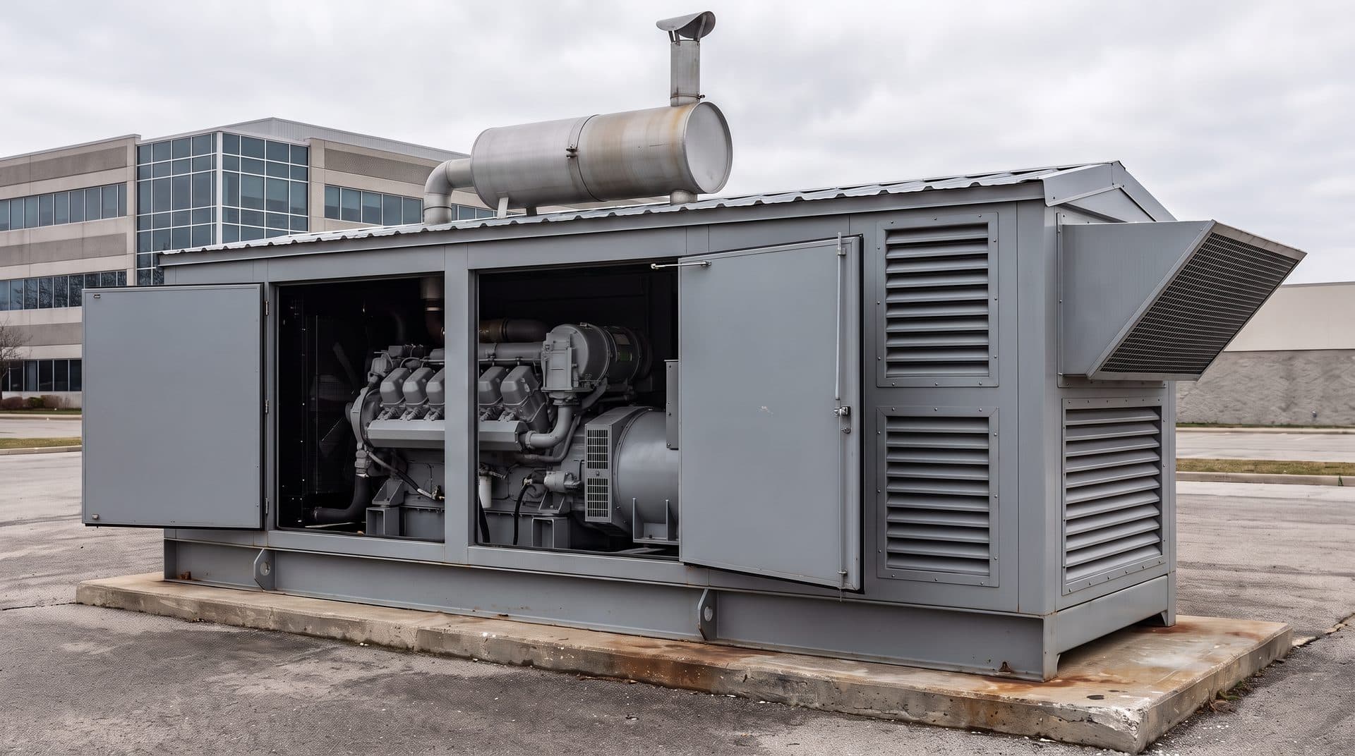
On an engine-driven generator set, the exhaust outlet and the enclosure’s cooling-air inlet and outlet are often the dominant noise paths. Each one is treated with a silencer, louver or baffle that also restricts the flow, so noise and pressure drop have to be designed together.
Firing frequency
Exhaust and intake noise is usually strongest at the engine’s firing frequency and its harmonics. For a four-stroke engine, firing frequency is the shaft speed in revolutions per second times half the number of cylinders: a six-cylinder engine at 1,800 rpm fires at 90 Hz, with harmonics at 180 and 270 Hz. Other engine orders can also produce significant tones.
Many generator sets with four-pole alternators run at 1,800 rpm for 60 Hz or 1,500 rpm for 50 Hz, so the main tones are low in frequency, where absorptive lining alone gives little attenuation.
Exhaust and intake silencers
Reactive elements — chambers and resonators — work best on low-frequency tones, and dissipative (lined) elements on mid- and high-frequency broadband noise. Many engine silencers combine both. Intakes are treated the same way, with intake silencers and Helmholtz or quarter-wave resonators; on turbocharged engines, turbocharger noise adds to the induction noise.
Back pressure and restriction
Every engine has a manufacturer-specified maximum exhaust back pressure. Exceeding it reduces power and raises fuel consumption and exhaust temperature. The piping, the bends, the silencer and the rain cap all add to the total. The intake side has its own maximum restriction, set by the engine manufacturer in the same way.
Generator-set enclosures
The enclosure has to pass large volumes of cooling and combustion air while keeping engine and radiator-fan noise inside. Longer splitter silencers with narrower airways attenuate more but add pressure drop, and the whole ventilation path must stay within the manufacturer’s allowable cooling-air restriction. A quieter layout that starves the radiator is not a solution.
Questions a simulation can answer
- What transmission loss will this silencer give across the frequencies that matter, before it is built?
- Will a quieter silencer still stay within the engine’s back-pressure limit?
- Where is the back pressure coming from: the piping, the bends, the silencer or the rain cap?
- How much do the intake and air filter restrict the engine, and where?
- Which ventilation-path layout is quietest while still giving the radiator enough air at full load?
- Given the engine and fan sound data, is this enclosure likely to meet the site’s sound limit?
Matching the method to the question
- Plane-wave models. Transfer-matrix models predict silencer transmission loss reliably below the first cross-mode cut-on frequency: about 1.84c/πD for a circular section, taken at the largest diameter and at the actual gas temperature. They are quick to run, so they suit early layout comparisons.
- 3-D finite- and boundary-element models. Needed above cut-on, where the sound field in large chambers is three-dimensional, and for enclosures, louvers and ventilation paths.
- Hot gas and mean flow. Hot exhaust gas has a higher speed of sound than ambient air, which shifts a muffler’s tuned frequencies upward. Mean flow also changes performance, so models use the actual gas temperature and flow.
- CFD for pressure drop. Steady RANS CFD is widely used to predict silencer pressure drop and flow distribution. Its accuracy depends on how perforated elements and porous materials are modeled, so those sub-models are checked against data.
What to send, and what comes back
What you send
- Geometry of the silencer, intake or enclosure, and the piping or ventilation path around it
- Engine data: speed, number of cylinders, and exhaust or intake flow rate and gas temperature at the operating points
- Source sound data where it exists: unsilenced exhaust or intake spectra, and engine and fan sound power
- The targets: attenuation or sound level, and the back-pressure or restriction limit
What comes back
- Predicted transmission loss, or levels at agreed positions where the source data allows
- Predicted back pressure or restriction, with a breakdown of where the losses occur
- A ranking of the variants on attenuation and pressure drop together
- A short written recommendation, with the model’s limitations stated
Please don’t send CAD through the website form. Files are exchanged after first contact.
Where this applies
- Generator Sets & Power GenerationExhaust silencers, rain caps, enclosures and ventilation paths for standby and prime-power sets.
- Filtration, Intake & Exhaust SystemsEngine air intakes, air filters, and intake and exhaust silencers.
Related services
- Acoustic Modeling & SimulationPredicts silencer transmission loss and enclosure sound levels.
- CFD Flow & Pressure DropPredicts back pressure and restriction through the same geometry.
- Aerodynamic Modeling & SimulationChecks cooling and radiator airflow through the enclosure.
- Noise Control & MitigationRanks the noise paths and compares fixes against the site limit.